Pcb easyeda tutorial designing complete
Table of Contents
Table of Contents
If you’re interested in building electronic gadgets, you’re going to need printed circuit boards. A PCB is a crucial component in any electronic project, and learning how to create your PCB layout is imperative. Whether you’re just getting started or already have some experience with PCB design, this post will provide you with valuable insights on how to draw PCB layouts like a pro.
The Pain Points of Drawing PCB Layouts
PCB design can be frustrating, especially for beginners. Designing a PCB requires attention to detail, and even the smallest mistake can cause the circuit to fail. Additionally, the software used to draw PCB layouts can be unintuitive and challenging to operate. Plus, understanding the various components and how they connect can be overwhelming, especially for someone new to electronic engineering.
How to Draw PCB Layouts
After deciding on the components required for your circuit, the first step to designing your PCB layout is to sketch a preliminary diagram of the circuit. You can use pen and paper or any other software like Eagle, KiCad, EasyEDA, etc. The goal is to determine the placement of each component, its location, and its connectivity to other components on the PCB board. After you have a rough drawing, you can start designing the PCB layout in software, following the below steps:
- Import your circuit diagram
- Lay out your components on the board
- Connect the components with copper traces
- Create ground planes and power planes
- Add text, logos, and designators
- Generate Gerber files for manufacturing
 The Importance of Proper Component Placement
Good component placement is critical, ensuring the integrity and longevity of the circuit. Always place the components in proximity to their ideal locations, reducing the likelihood of signal degradation, noise interference, and electrical interference, which can cause the circuit to fail. When arranging components, consider their functionality, data flow, size, and heat generation rating.
 Ground Planes and Power Planes
Ground planes and power planes should cover the entire PCB’s surface. These planes help reduce the noise on the board and provide stable voltage to components, making the circuit reliable. Ground planes are typically located behind the board while power planes are usually located near high-power consuming components such as microcontrollers or power transistors.
Choosing the Right Trace Width and Spacing
The width of the copper trace chosen is essential, as too narrow a trace can result in too much resistance, causing heat generation and board failure. The thickness of the copper trace must be thick enough to carry low voltage and small current, such as signal and control traces. Larger current-carrying traces such as power and ground planes must be thicker to reduce electrical resistance and heat generation.
 Always Double-Check Before Sending to Manufacturing
Before sending your design for manufacturing, make sure to double-check the dimensions, orientation and connectivity of each component, traces and planes. Carefully examine the layout to ensure that there are no accidental duplication of traces, no missing traces, components, and that the dimensions of the board correspond to your requirements.
Question and Answer Section
Q: Can I create PCB layout without software?
A: Yes, you can create a PCB layout without software. However, creating it with software makes things much more comfortable and more precise. There are free software you can use such as Fritzing, EagleCAD, KiCad, and EasyEDA.
Q: How do I measure the trace width and spacing?
A: You can measure the trace width and spacing using a digital caliper or a magnifying glass with a ruler. Additionally, most PCB design software can automatically calculate the trace width and spacing based on the required current and voltage ratings.
Q: How do I choose the right components for the circuit?
A: Choosing the right component requires an understanding of circuit characteristics such as voltage, current, power, and frequency. Before selecting components, define your circuit’s requirements based on your project’s goals and specifications.
Q: Can I outsource PCB manufacturing?
A: Yes, you can outsource PCB manufacturing to a professional PCB manufacturing company. Outsourcing PCB production provides a high level of accuracy, reliability, and faster delivery times. Mostly, PCB manufacturers in Asia are so much better at PCB manufacturing compared to other continents.
Conclusion of How to Draw PCB Layout
Drawing a PCB layout may seem overwhelming for a beginner, but once you understand the basic concepts, it becomes easy. Proper component placement, trace width and spacing, ground planes, and power planes are all essential factors to consider when designing your PCB. With good planning and software, you can have your custom PCB layout ready in a short time. A perfect PCB layout is the foundation of a successful circuit design, so it’s crucial to put in the time and effort to get it right.
Gallery
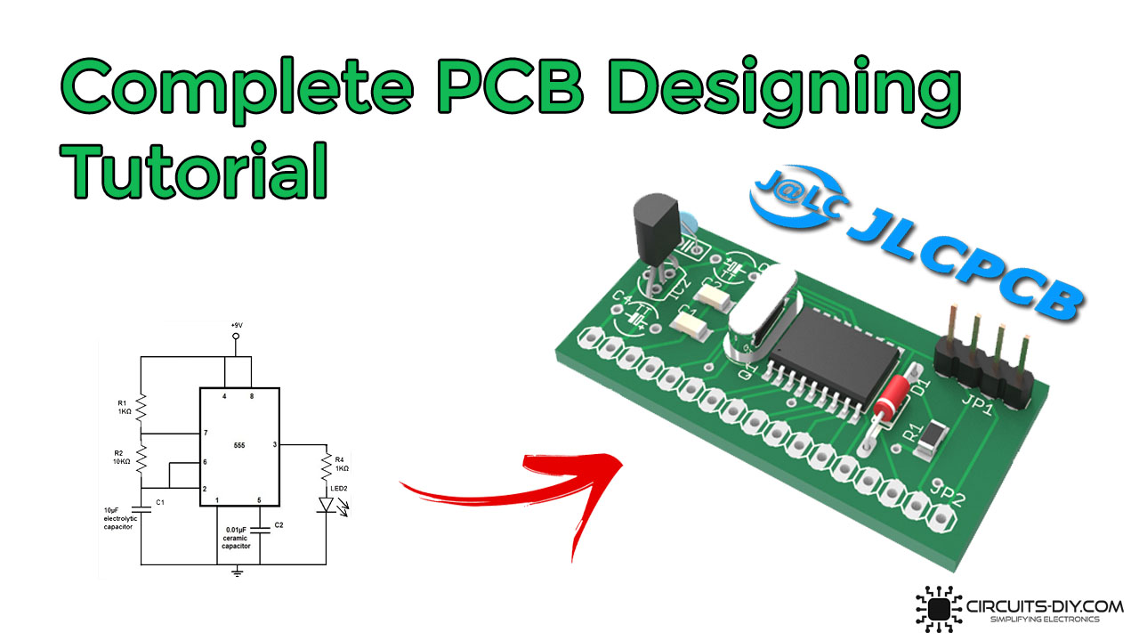
Complete PCB Designing Tutorial Using EasyEDA PCB Design Tool

Photo Credit by: bing.com / pcb easyeda tutorial designing complete
Courses | ACDC Tech - Advance Circuit Development Center

Photo Credit by: bing.com / pcb
Make Sure To Consider These Factors When Creating A PCB Layout - Blog

Photo Credit by: bing.com / pcb layout
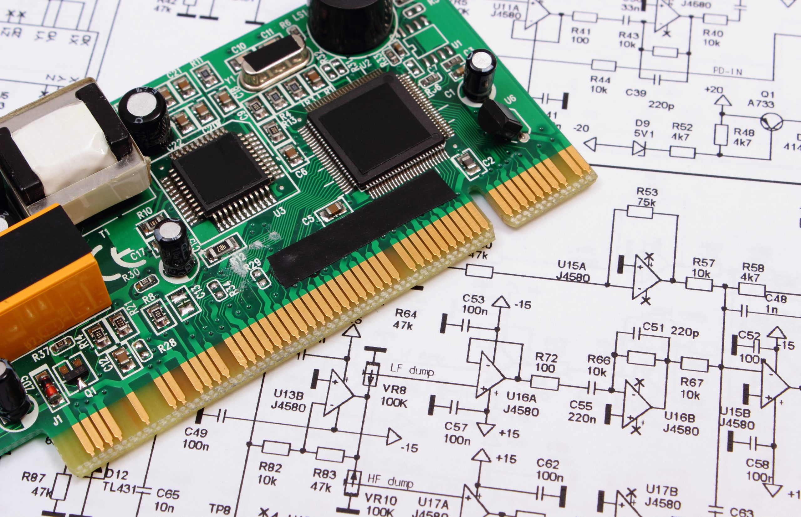
Draw Schematic From Pcb | Drawer Gallery

Photo Credit by: bing.com / schematic printen 123mm 85mm wymiary rzeczywiste elektroda pngkey 41kb
Mastering The Art Of PCB Design Basics | Sierra Circuits

Photo Credit by: bing.com / diagram stampato circuito schematic lying diagramma elektronika kringsraad gedrukte liggen circuits clone sierra mastering basics kmh protoexpress


